
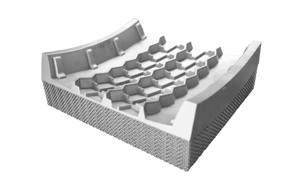
Preparing a metal component for additive manufacturing involves more than exporting a three-dimensional model. Engineers must consider geometry, material properties, build orientation, support structures, and finishing requirements before production begins. These decisions can affect dimensional accuracy, material consumption, printing time, and final part performance.
For manufacturers developing prototypes or customized industrial parts, a structured preparation workflow helps reduce avoidable errors and improve production efficiency. Selecting suitable metal additive manufacturing solutions also requires careful consideration of design constraints, material compatibility, and post-processing needs.
Review Functional Requirements and CAD Geometry
The first step is to define the component’s intended function. Engineers should document operating loads, working temperatures, environmental exposure, critical dimensions, and service-life requirements. These details guide material selection and design decisions.
Next, the CAD model needs a technical review. It should contain complete geometry without unintended gaps, overlapping surfaces, or invalid features that could cause problems during file conversion. Wall thicknesses, narrow passages, enclosed cavities, and thin projections deserve particular attention.
Teams should also distinguish critical interfaces from non-critical surfaces. This helps establish dimensional tolerances and identify areas that may require machining after printing. Resolving design issues early can reduce revisions and prevent avoidable production delays.
Select a Suitable Metal Powder
Material selection should reflect the component’s operating environment and performance requirements. Common options for metal powder bed fusion include aluminum alloys, titanium alloys, stainless steels, tool steels, cobalt-chromium alloys, and nickel-based superalloys.
Engineers should compare strength, fatigue behavior, corrosion resistance, thermal performance, and finishing requirements. The specific alloy grade matters because materials within the same family can have different properties. Teams must also confirm that the selected powder is compatible with the printing system and its qualified process parameters.
Material availability alone does not establish suitability. For demanding applications, engineers should review relevant material data and determine what testing or qualification is necessary to verify the finished component.
Optimize the Design for Additive Manufacturing
Preparing the metal 3D printing process starts with a design that can be manufactured and finished reliably. Design for additive manufacturing (DfAM) evaluates how geometry, support access, and machining allowances affect the production route.
Engineers may consolidate several components, simplify assemblies, or introduce internal channels and lattice structures where these features provide a clear functional benefit. For example, complex cooling passages can improve heat distribution in certain mold inserts, while lightweight structures may reduce mass in selected engineering components.
However, greater geometric complexity does not automatically improve performance. Thin walls, sharp transitions, inaccessible cavities, and unsupported overhangs can increase manufacturing risks. Designers should balance functional requirements with printability, inspection access, and finishing needs.
Internal cavities also require a practical powder-removal route. Where precision interfaces need machining, the CAD model should include suitable machining allowances. Planning these details during design helps avoid costly changes after printing.
Choose Build Orientation and Support Structures
Build orientation determines how the component is positioned and formed layer by layer. It can influence support volume, surface quality, thermal behavior, build time, and post-processing effort.
There is rarely one ideal orientation for every requirement. Positioning a critical surface differently may reduce support contact, while another orientation may improve stability or lower the build height. Engineers should compare these trade-offs against functional surfaces, dimensional tolerances, and production constraints.
Support structures help stabilize selected features and manage heat transfer during laser processing. They can also restrain deformation during the build. However, supports consume material and require removal, which may leave contact marks or add finishing work.
A sound support strategy considers overhangs, accessibility, and potential distortion. Engineering review and suitable simulation tools can help identify risks before production begins.
Prepare the Build File and Printing Parameters
Once the design and orientation are approved, the model is converted into a suitable manufacturing file and prepared in slicing software. The software divides the geometry into layers and generates scanning instructions for the printing system.
Before slicing, engineers should verify file integrity, model scale, units, orientation, and build-volume compatibility. Incorrect units or unsuitable exports can cause serious production problems even when the original CAD model is correct.
Process parameters also require careful control. Laser power, scanning strategy, and layer thickness influence how the material melts and solidifies. Settings must match the machine, alloy, geometry, and qualified process requirements. A parameter combination suitable for one component should not automatically be applied to another.
The final build review should confirm that the component and its supports fit within the available build area. For production batches, the arrangement of multiple parts should also be checked.
Plan Post-Processing and Quality Inspection
Printing is only one stage of metal additive manufacturing. Depending on the component and process, subsequent operations may include loose-powder removal, build-platform separation, support removal, heat treatment, machining, and surface finishing.
The production plan should identify the required operations before printing begins. Engineers need to confirm that supports can be accessed and removed, internal passages can be cleaned, and critical surfaces can achieve their specified tolerances.
Inspection requirements should also be established in advance. Dimensional measurement, visual inspection, mechanical testing, or other verification methods may be necessary depending on the application. Safety-critical components require particular attention to documented process control and qualification.
Coordinate with a Manufacturing Partner
A practical preparation workflow connects design decisions with manufacturing capabilities. When requesting a technical review, engineering teams should provide a 3D CAD model, material requirements, critical dimensions, operating conditions, and estimated production volume.
LiMN 3D provides metal 3D printing equipment, customized printing services, and technical support for industrial applications including aerospace, mold manufacturing, energy, automation, and consumer electronics. Its metal 3D printing process includes file checks, printing recommendations, post-processing, and quality control.
Manufacturers evaluating LiMN 3D should submit approved designs and acceptance requirements. The proposed workflow should identify necessary design changes, inspection steps, and responsibilities before production begins.
